Understanding Automotive Electricity
The Inoperative Blower Motor
Every working electrical circuit on a vehicle requires four core components: a power source to supply electrical pressure, protection to guard against overcurrent, a control device to toggle current flow, and a load device to convert electrical energy into mechanical work or heat. Finally, current must travel through a return path back to the battery negative post. If any single point along this path is interrupted, current stops flowing instantly throughout the entire loop.
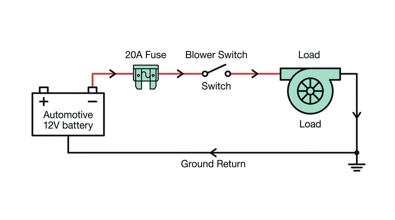
On a functional, switched-on circuit, the load device receives system voltage (12.0 V to 14.5 V). Measuring 0.00 V directly across the load terminals while switched ON indicates an open circuit upstream in the feed path or a complete loss of the ground return connection.

Check your understanding
A technician measures 0.00 V directly across a switched-on blower motor's terminals. Battery voltage is 12.6 V. What does this reading prove?