Voltage Drop Test
Measures the voltage lost across a live circuit section to find high resistance that a standard ohm meter cannot detect.
What this test tells you
When to use it
- When a component operates sluggishly, dimly, or intermittently despite having correct source voltage at rest.
- When diagnosing high-resistance ground connections or poor earth straps.
- When verifying heavy-current feed cables for starters, alternators, or electric power steering pumps.
Safety
- Ensure hands, clothing, and meter leads stay clear of moving drive belts, pulleys, and cooling fans.
- Do not short live positive supply connections directly to vehicle earth when placing probes.
- Avoid probing through outer insulation unless properly sealed with liquid electrical tape afterward to prevent moisture ingress and corrosion.
Vehicle setup
- Position the vehicle on a level surface with the handbrake firmly applied and transmission in neutral or park.
- Switch the ignition on and switch on the specific circuit or component under test so current actively flows.
- Ensure all high-current loads relevant to the circuit (e.g., blower motor, headlamps, starter) are drawing operational current.
Meter setup
- Tool
- Digital Multimeter
- Function
- DC Voltage (V DC or mV DC)
- Range
- Auto-range or 2V DC / 200mV DC scale
- Sockets
- Red lead in V/Ω socket, black lead in COM socket
Practise it — interactive simulation
Starter positive circuit
Crank the engine and measure the loss between the battery and the starter.
- GND — Battery → BPOS
- BPOS — Positive cable → J1
- J1 — Cable joint → J2
- J2 — Solenoid contacts → SB
- SB — Starter motor → SG
- SG — Engine earth strap → ENG
- ENG — Battery earth lead → GND
Loading the interactive circuit…
RED Upstream (battery positive side) of the suspected wire, connector, switch, or earth strap
BLACK Downstream (load or earthing point side) of the suspected wire, connector, switch, or earth strap
Probes must span only the specific section of wire or component being tested while current flows through it.
Step by step
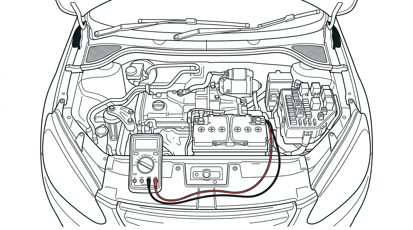
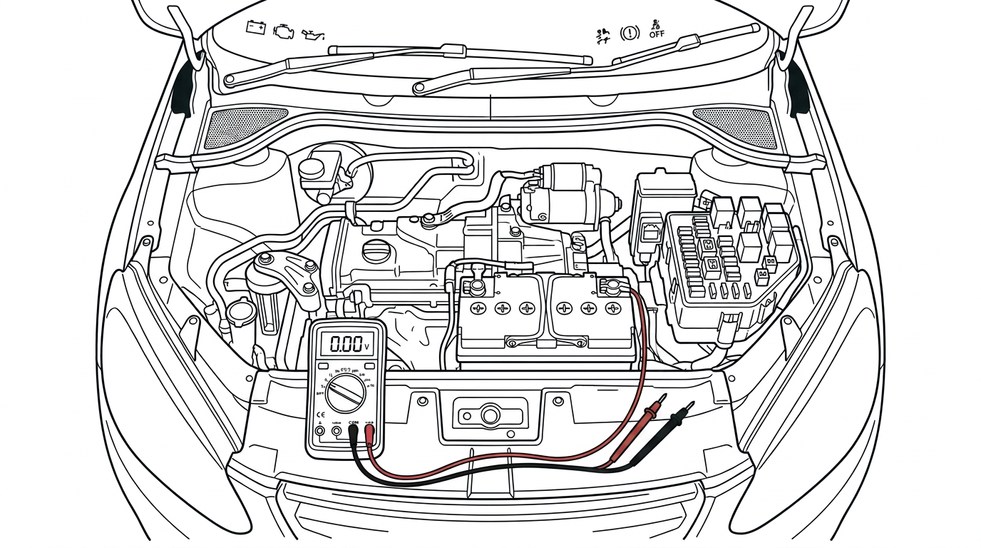
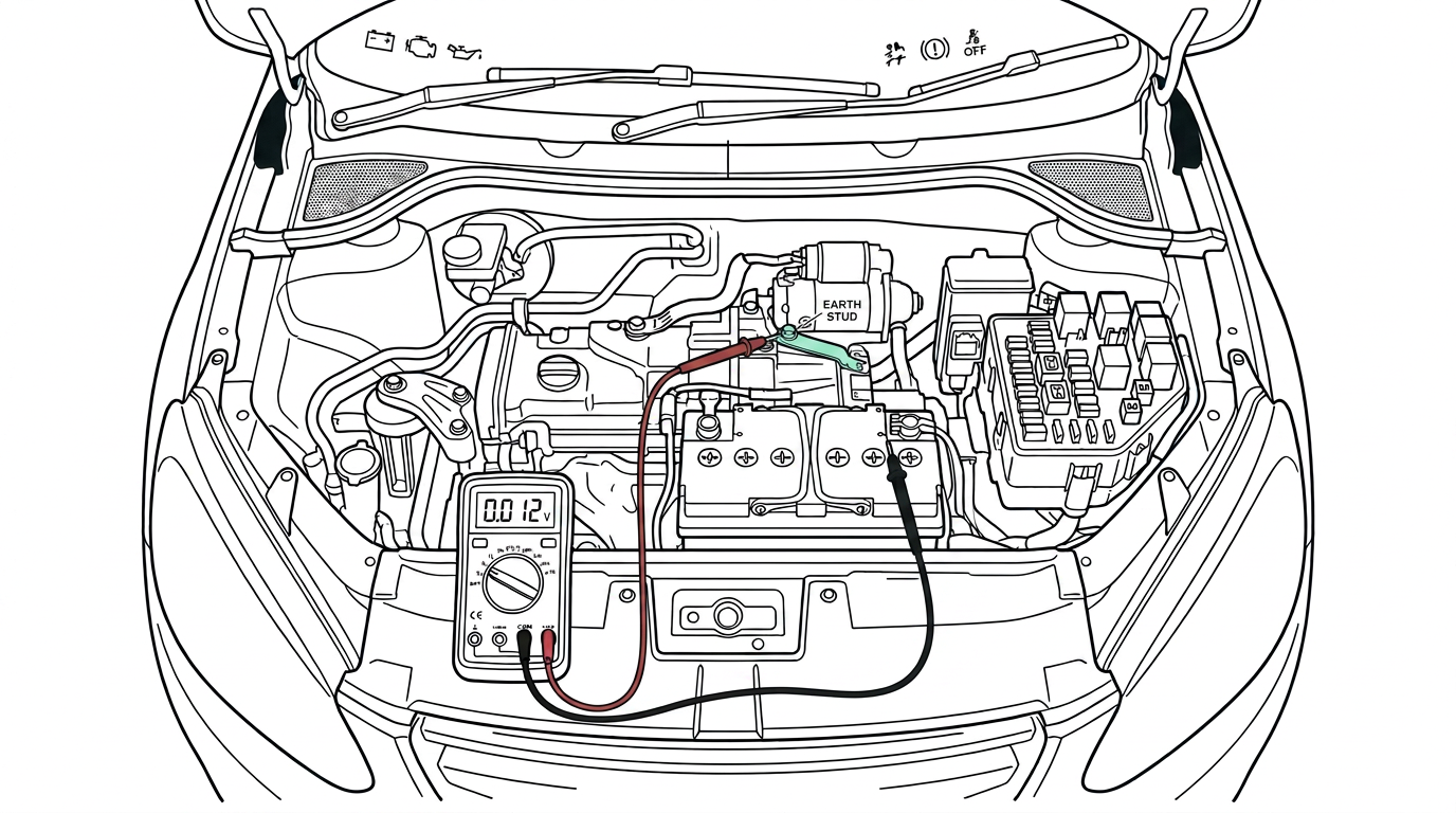
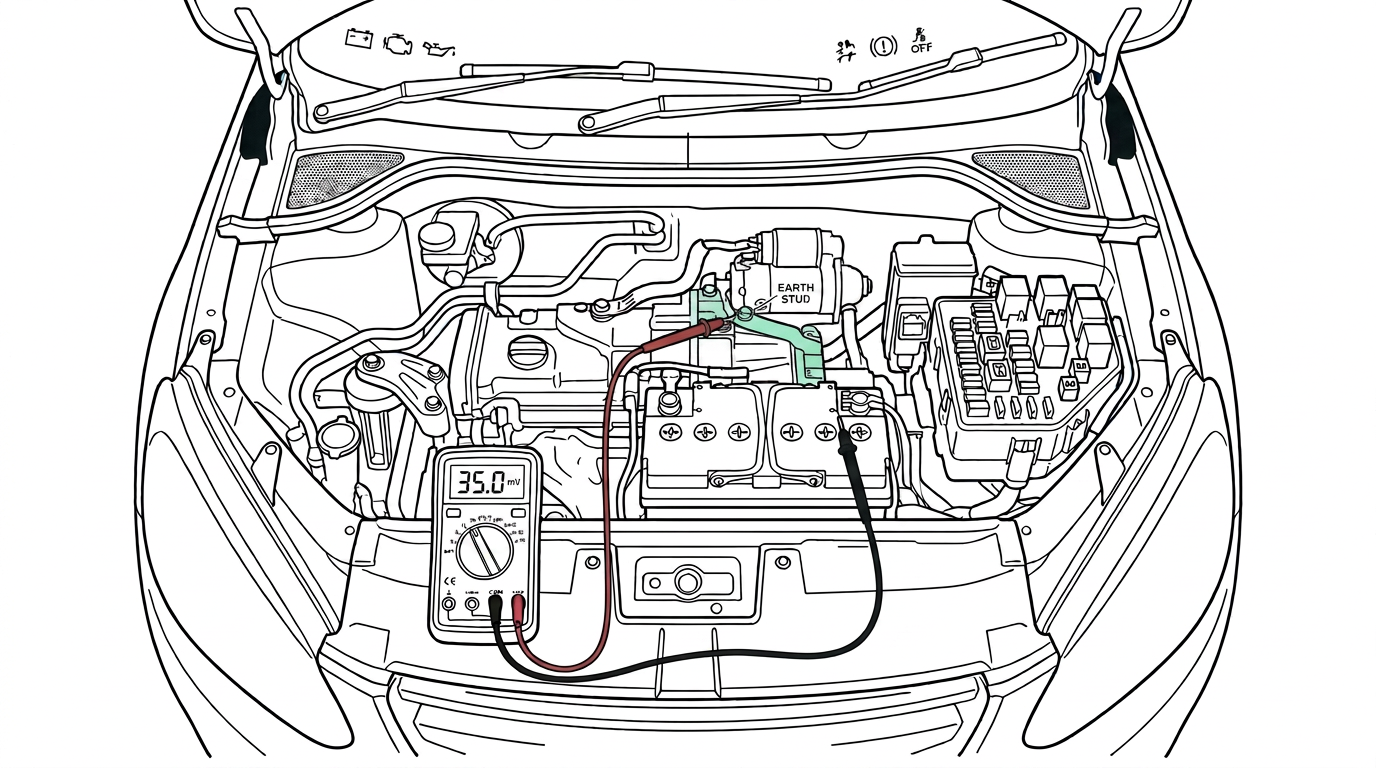
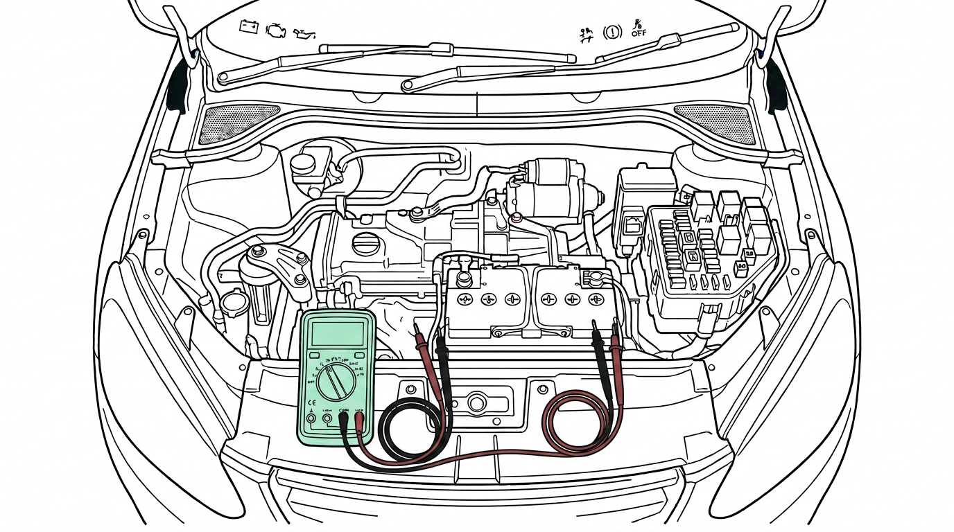
Step 1 · Set Meter and Select Circuit
Select DC Volts on the digital multimeter and plug the red lead into V and the black lead into COM. Identify the earth strap connecting the engine casing to the chassis.
Tap the numbered markers on the picture for the exact contact points.
- Meter
- DC Voltage (V DC)
Procedure
- Set the digital multimeter to DC voltage mode and insert the test leads into the V and COM sockets.
- Identify the specific section of the live circuit under test, such as a wire segment, switch contact, or earth connection.
- Turn on the circuit power supply and activate the load so full operating current flows through the circuit.
- Place the red meter probe on the upstream side (closer to battery positive) of the conductor segment under test.
- Place the black meter probe on the downstream side (closer to battery earth or load) of the same conductor segment.
- Observe and record the DC voltage reading on the multimeter display while current is actively flowing.
- If necessary, switch meter to millivolt (mV) range for small readings to increase precision on low-drop connections.
- Compare the measured voltage drop against maximum acceptable limits (typically under 100 mV across connections or switches, under 200 mV across heavy earth straps).
- Deactivate the circuit, repair or clean any connection showing excessive voltage drop, and repeat the test to confirm repair.
Normal result
0.00 V to 0.10 V (0 to 100 mV) across a good switch, connector, or wiring run under standard load; up to 0.20 V (200 mV) on high-current earth straps during operation.
Fault result
Greater than 0.50 V across a single wire or connection point, or total circuit voltage drop exceeding 10% of supply voltage.
Interpretation
If0.00 V to 0.05 V across connection
ThenConnection is in excellent condition with minimal resistance under load.
NextProceed to test other sections of the circuit or test the load device itself.
If0.10 V to 0.40 V across connector or switch
ThenModerate resistance present due to minor oxidation, light corrosion, or poor terminal tension.
NextClean terminals, adjust pin tension, apply dielectric grease, and re-test.
IfGreater than 0.50 V across wire or switch
ThenHigh resistance fault present caused by corroded crimps, broken wire strands, or pitted switch contacts.
NextReplace or repair the damaged wiring segment, connector terminal, or switch assembly.
IfFull battery voltage (e.g. 12.6 V) across component
ThenOpen circuit fault on the tested segment while current is demanded.
NextLocate the break or completely open switch/connection point along that specific segment.
Common mistakes
- Testing voltage drop on an inactive (de-energised) circuit, which always shows 0.00 V regardless of resistance because no current flows.
- Using an ohmmeter on a dead circuit instead of a live voltage drop test, which misses resistance under actual current load.
- Measuring from power to earth across a load component instead of across a single conductor or connection point, which measures load operating voltage rather than voltage drop along the feed/return wire.