Power and Ground Check
The first structured step at any dead component: does it have supply, and does it have ground?
What this test tells you
When to use it
- Any component that does nothing at all
- Before condemning a module, motor, sensor or actuator
- Whenever a scan tool reports an open circuit fault
Safety
- Back-probe rather than piercing wire insulation, which invites future corrosion
- Take care around airbag and high-voltage circuits — do not probe them
- Watch for the component operating unexpectedly once you restore its supply
Vehicle setup
- Ignition in the state that should energise the circuit
- Any switch that controls the circuit switched on
- Connector accessible for back-probing, ideally still plugged in
Meter setup
- Tool
- Digital multimeter
- Function
- DC volts
- Range
- Auto range or 20 V DC
- Sockets
- Red in VΩ, black in COM
Practise it — interactive simulation
Power and ground check
Confirm supply and return at the component before touching anything else.
- GND — Battery → BPOS
- BPOS — Fuse 15 A → FOUT
- FOUT — Relay contacts 30–87 → R87
- R87 — Supply wire → LP
- LP — Component (21 W lamp) → LG
- LG — Earth point E12 → GND
Loading the interactive circuit…
RED Supply pin at the component connector
BLACK Battery negative post
Referencing the battery, not a local ground, means one reading tests both supply and ground path integrity
RED Battery positive post
BLACK Ground pin at the component connector
Should read near battery voltage if the ground path is good
RED Supply pin at the component connector
BLACK Ground pin at the same connector
Available voltage at the component itself
Step by step

Step 1 · Get to the connector
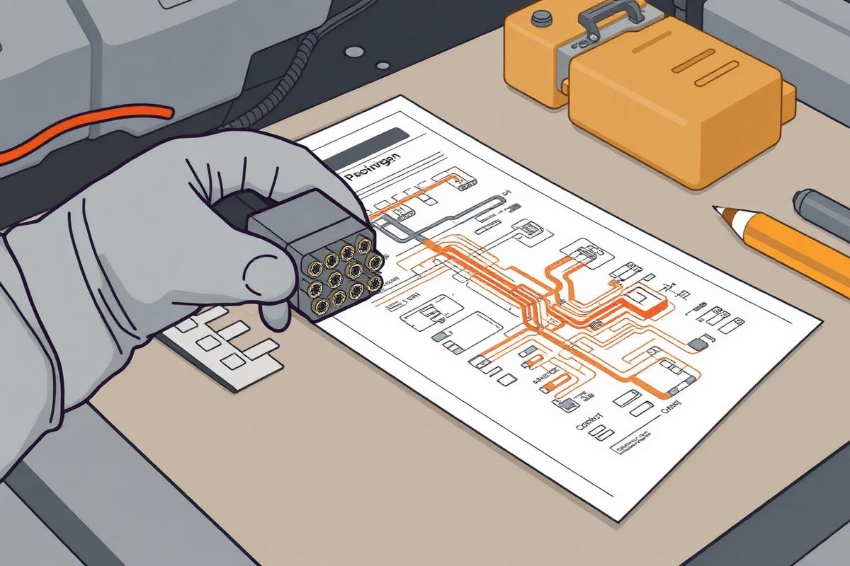
Unplug the component and identify its supply and earth pins from the wiring diagram before you probe anything.
Procedure
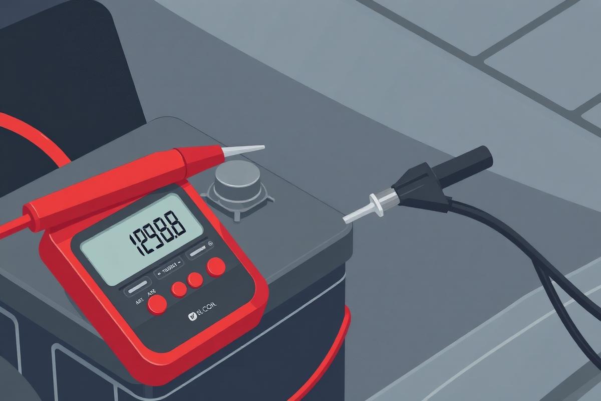
- Confirm battery voltage at the posts and note it
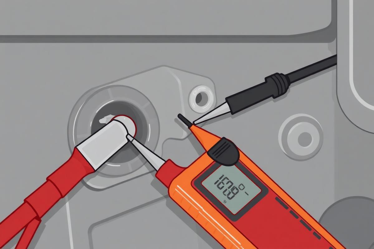
- Back-probe the supply pin with red, black on battery negative, and read
- Move red to battery positive and black to the ground pin, and read
- Finally measure across the component's own two pins
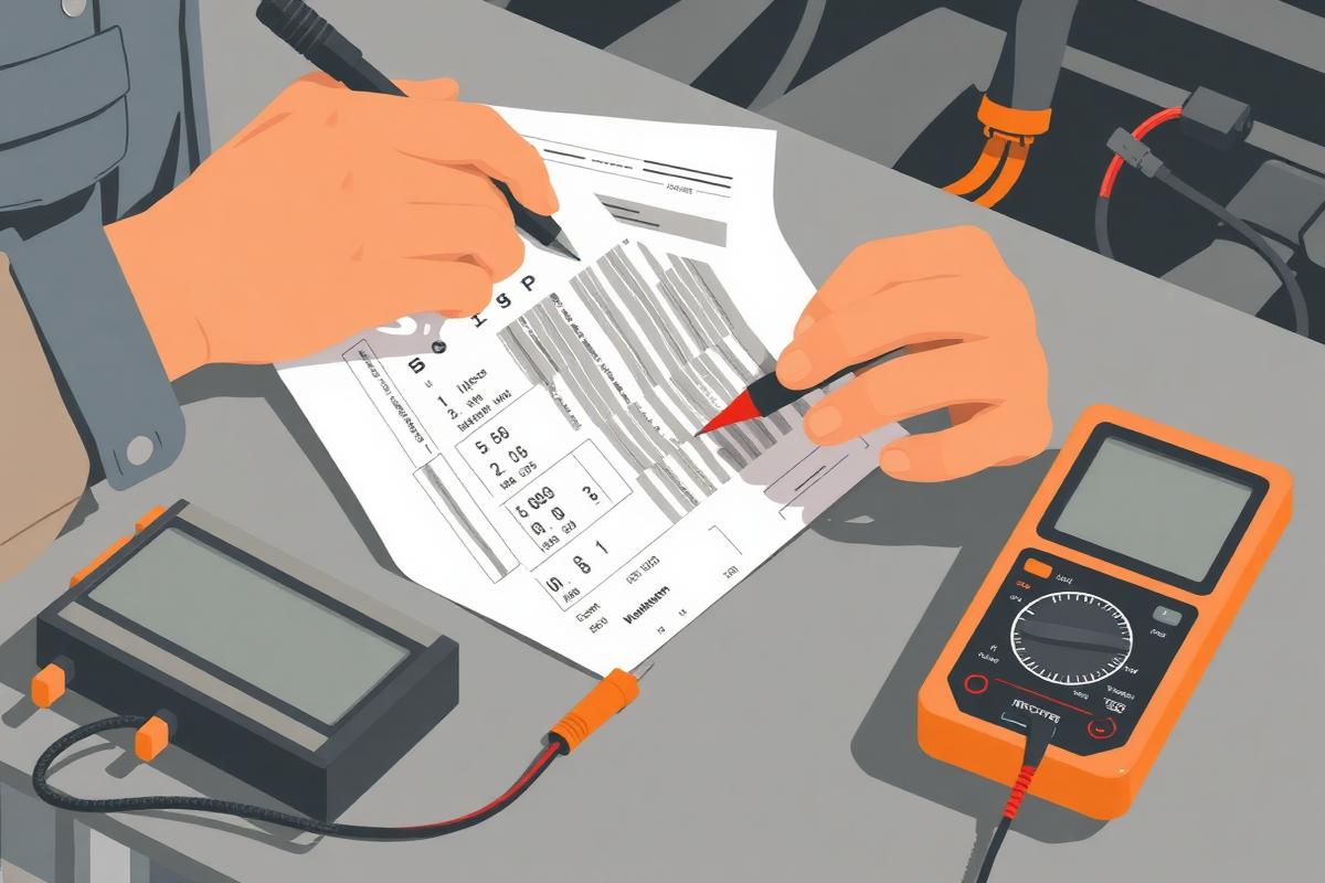
- Compare all three readings to the battery voltage you recorded
- If supply and ground are both good, load-test the circuit with a test lamp or the component itself before condemning the component
Normal result
All three readings within about 0.5 V of battery voltage while the circuit is commanded on.
Fault result
Any reading substantially below battery voltage, or zero.
Interpretation
IfNo voltage on the supply pin
ThenThe feed is broken upstream — fuse, relay, switch or wiring
NextWork back towards the fuse box, testing at each junction
IfSupply present, but battery positive to component ground reads low or zero
ThenThe ground path is broken or high resistance
NextTrace the ground to its earth point, clean and retest
IfBoth good and the component still does nothing
ThenThe component itself, or its control side, has failed
NextResistance test the component and check any control signal
IfGood with the meter, dead with a load applied
ThenHigh resistance the meter cannot see — a phantom supply
NextRepeat with a test lamp or move to a voltage drop test under load
Common mistakes
- Referencing a local ground instead of the battery, which hides a ground fault
- Testing with the circuit not commanded on
- Accepting a voltage reading as proof of a healthy supply — a meter draws almost no current and reads through corrosion
- Piercing insulation and leaving an entry point for water