Alternator Diode Ripple Test
Looks for AC ripple caused by failed rectifier diodes.
What this test tells you
When to use it
- Charging voltage passes but the battery still goes flat
- Whine through the radio that rises and falls with engine speed
- Unrelated modules throwing communication or implausible-signal faults
- Alternator output current measures around a third low
Safety
- Belt and fan hazards as with any running-engine test
- Scope leads must be routed and secured away from moving parts
- Do not disconnect the battery or the B+ cable while running
Vehicle setup
- Engine at operating temperature and idling
- Battery healthy; a poor battery damps ripple and hides the fault
- Heavy electrical loads available to switch on — ripple grows with output
Meter setup
- Tool
- Digital multimeter for the quick check, oscilloscope for the diagnosis
- Function
- AC volts on the meter; DC coupled, 500 mV/div on the scope
- Range
- AC millivolts; scope timebase around 5 ms/div
- Sockets
- Red in VΩ, black in COM
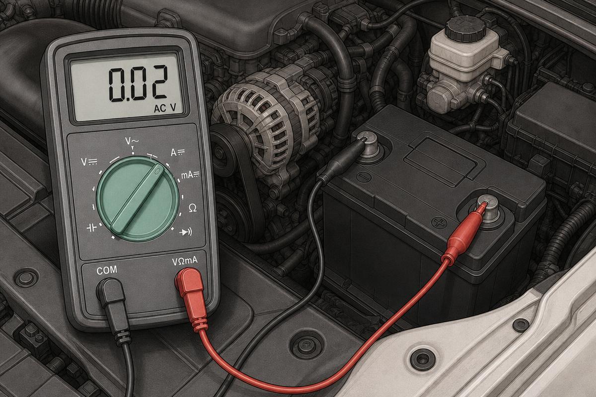
RED Battery positive post
BLACK Battery negative post
The meter's AC range ignores the DC and reports only the alternating component
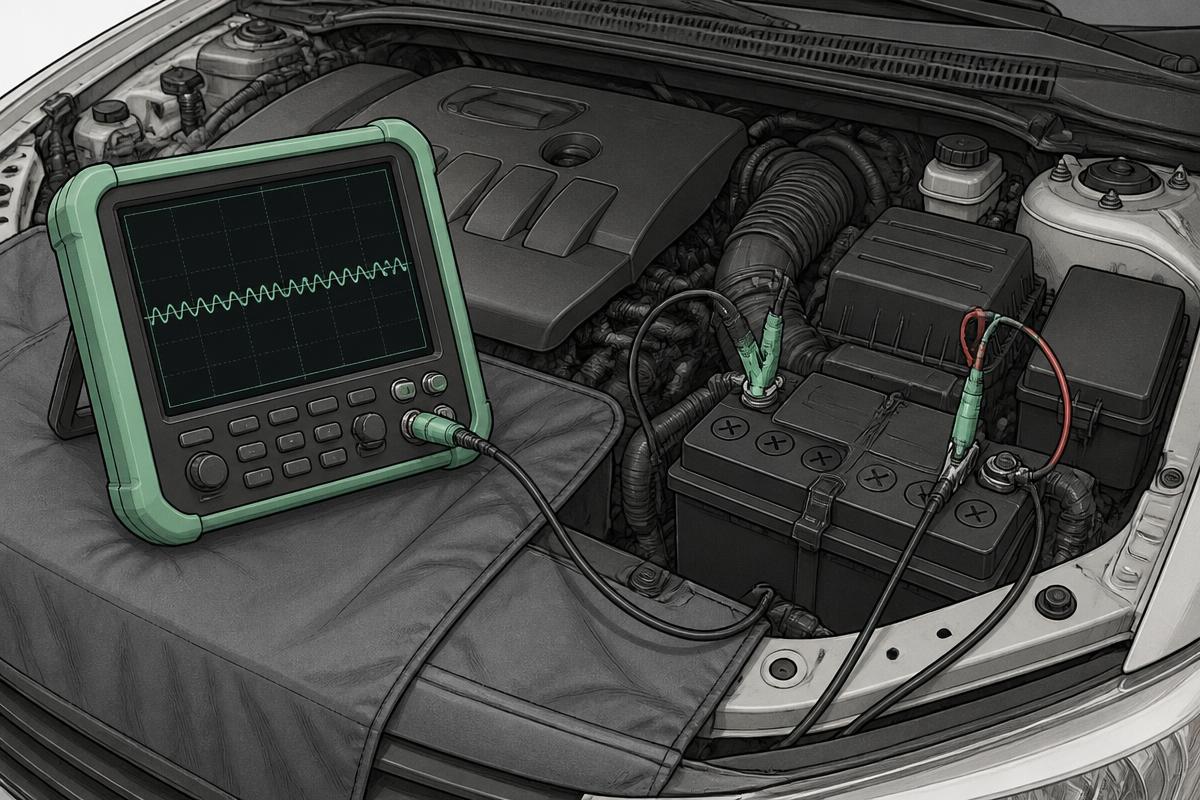
RED Scope channel A on the alternator B+ stud
BLACK Scope earth on the alternator casing
Measuring at the alternator shows the waveform before the battery smooths it
Step by step
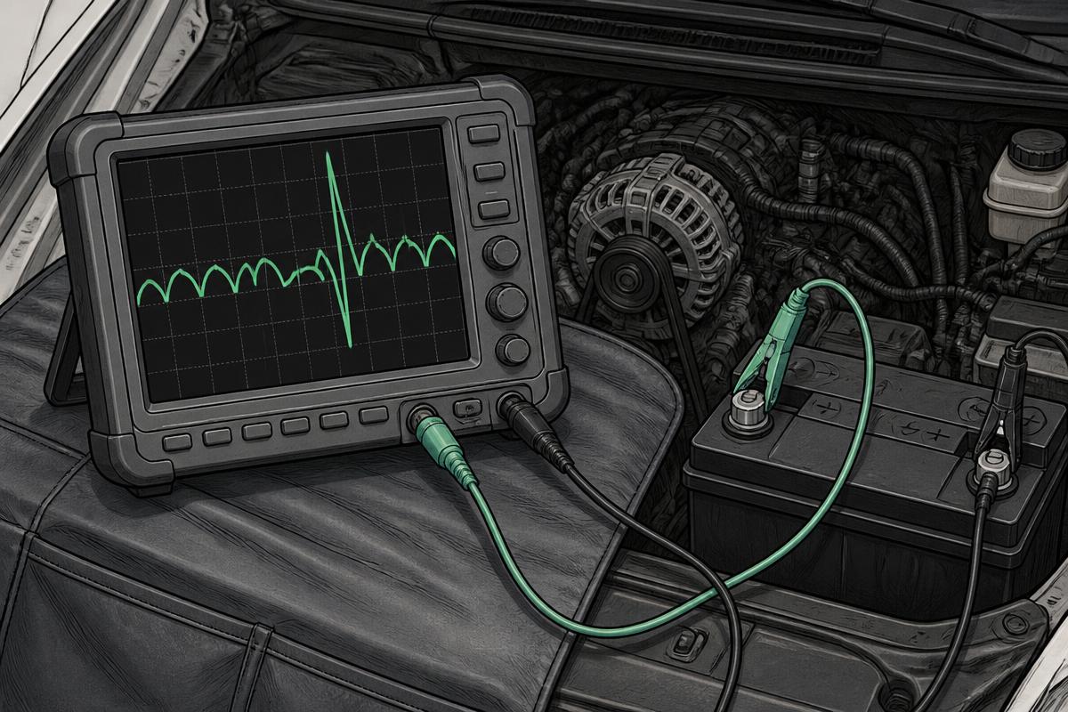
Step 1 · Know what you are testing
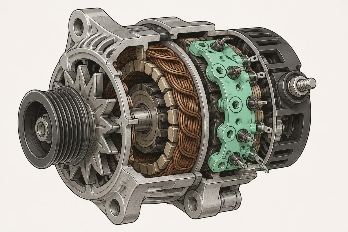
The stator makes three-phase AC; six diodes in the rectifier pack turn it into DC. Lose one diode and AC leaks into the vehicle's supply.
Tap the numbered markers on the picture for the exact contact points.
Procedure
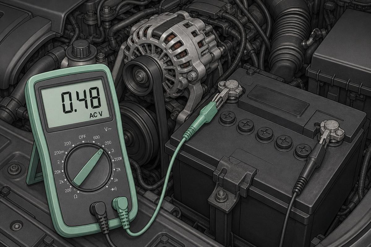
- Engine running, set the meter to AC volts and clip it across the battery
- Read the AC voltage at idle with no loads applied
- Switch on headlights, blower and heated rear screen and read it again at 2000 rpm
- If the AC figure is high, move to the scope for the pattern
- Connect the scope to the alternator B+ and casing, DC coupled
- Capture the ripple waveform at 2000 rpm under load
- Count the humps: six even peaks per cycle is a healthy rectifier
Normal result
Under 0.1 V AC at the battery — most healthy systems sit around 0.02–0.05 V. On the scope, an even six-hump pattern of low amplitude, typically under 500 mV peak to peak.
Fault result
Above 0.5 V AC at the battery, or a scope trace with a missing hump, an oversized spike, or an amplitude several volts peak to peak.
Interpretation
IfUnder 0.1 V AC
ThenRectifier is doing its job
NextLook elsewhere: drain, battery capacity, or cable drop
If0.1–0.5 V AC
ThenRipple rising — early diode degradation or heavy load on an older alternator
NextScope it and compare against output current
IfAbove 0.5 V AC with a missing hump on the scope
ThenOpen rectifier diode; output capacity will also be roughly a third down
NextReplace the alternator or rectifier pack
IfLarge spikes below the zero line
ThenShorted diode — heavy AC into the DC system, hard on every module
NextReplace immediately; it can damage electronics
IfHigh ripple but a clean pattern
ThenOften a poor battery or a bad connection failing to smooth the output
NextTest the battery and run the charging circuit drop test
Common mistakes
- Measuring with the meter on DC volts and seeing nothing wrong
- Testing at idle with no loads, where ripple is smallest
- Testing with the battery disconnected or a poor connection, which exaggerates the reading
- Condemning the alternator on a high AC reading alone without checking the connections
- Ignoring a customer's radio whine complaint as unrelated — it is often the first symptom