Charging Circuit Voltage Drop
Checks the alternator-to-battery cable and ground under charging load.
What this test tells you
When to use it
- Voltage at the alternator is clearly higher than at the battery
- Undercharging with a healthy alternator output current
- After any charging fault repair, to prove the whole path
- Hot or discoloured B+ terminal, fusible link or main fuse box connection
Safety
- The B+ cable is permanently live — do not let a probe bridge it to anything
- Route long leads clear of the belt, fan and exhaust
- The alternator body gets very hot in use
Vehicle setup
- Engine at operating temperature and running
- Heavy loads switched on so real charging current is flowing — no current, no drop
- Battery in reasonable state of charge
Meter setup
- Tool
- Digital multimeter with long leads
- Function
- DC volts
- Range
- Auto range or millivolts — expect hundredths of a volt
- Sockets
- Red in VΩ, black in COM
Probe placement
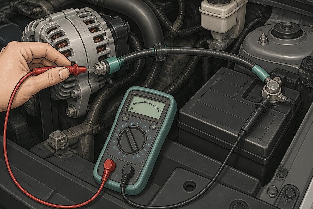
RED Alternator B+ output stud
BLACK Battery positive post
Feed side: the whole positive path including the fusible link, in one measurement
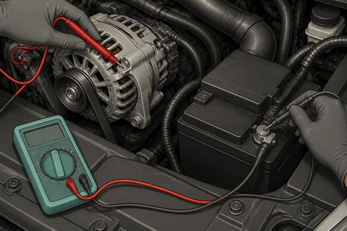
RED Alternator casing, on bare metal
BLACK Battery negative post
Return side: the alternator's ground path back to the battery
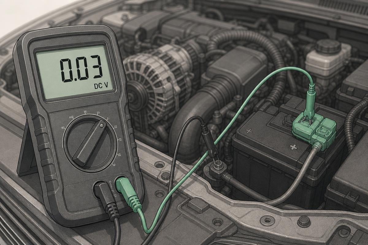
RED One side of the fusible link or main fuse
BLACK The other side of the same link
Halving down once a side is known to be high
Step by step
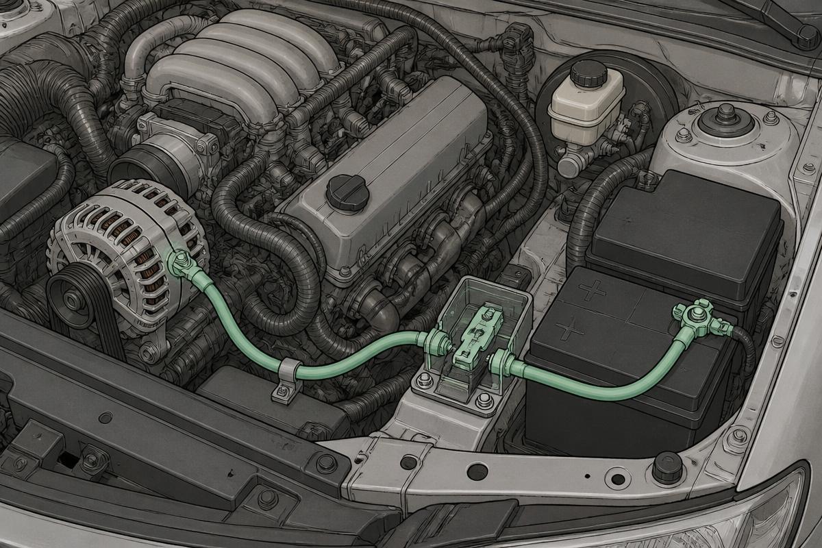
Step 1 · Map the charging loop
Feed side: alternator B+ stud, heavy cable, fusible link, battery positive. Return side: alternator casing, mountings, engine and body bonding, battery negative.
Tap the numbered markers on the picture for the exact contact points.
Procedure
- Start the engine and switch on headlights, blower and heated rear screen to draw current
- Hold around 2000 rpm so the alternator is genuinely working
- Measure the feed side: red on the alternator B+ stud, black on the battery positive post
- Record the reading while the loads are on
- Measure the return side: red on the alternator casing, black on the battery negative post
- If either side is out of spec, measure each joint in that path on its own
- Clean or replace the offending joint, then repeat both measurements
Normal result
Under 0.2 V on the feed side and under 0.1 V on the ground side while charging under load. Total loss around the loop should stay under 0.3 V.
Fault result
Above 0.3 V on either side, or a measurable difference between charging voltage at the alternator and at the battery of more than a couple of tenths.
Interpretation
IfBoth sides within limits
ThenThe cabling is sound
NextLook at the alternator output, the battery or the charging strategy
IfFeed side high
ThenResistance in the B+ cable, its terminals or the fusible link
NextMeasure each joint; clean or replace the worst one and retest
IfGround side high
ThenThe alternator mounting or the engine-to-body bonding is not carrying return current
NextRun the main earth strap test and clean the alternator mounting faces
IfBoth high
ThenGeneral corrosion through the charging loop, common on older or coastal vehicles
NextRefresh every joint in the loop rather than the worst one only
IfTerminal warm or discoloured with a high reading
ThenThe joint is dissipating real power and is on its way to failing completely
NextReplace the terminal or cable — cleaning a heat-damaged joint rarely lasts
Common mistakes
- Testing with no electrical load, where every joint reads perfect
- Measuring only the positive side and missing a ground fault
- Probing the cable insulation crimp instead of the terminal metal
- Blaming the alternator for undercharging caused by a corroded fusible link
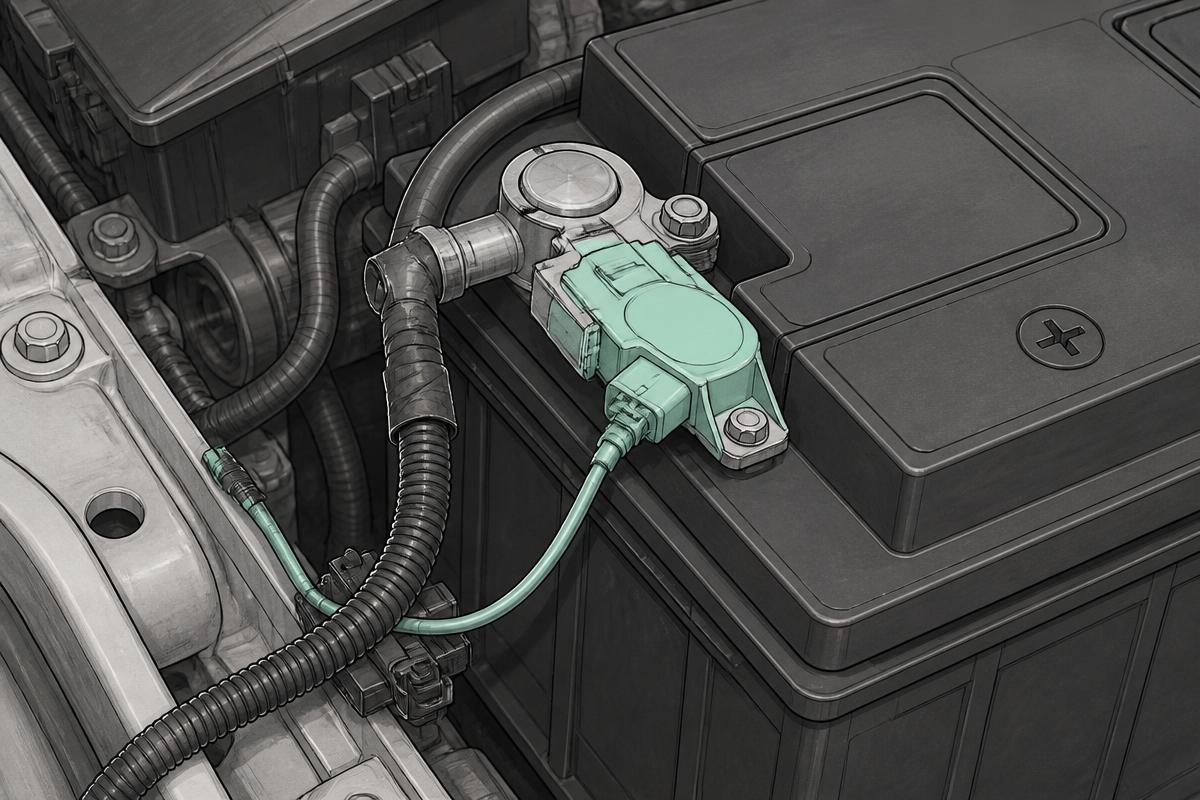
- Forgetting the intelligent battery sensor in the negative path on later vehicles