Resistance Test
Measures the resistance of a disconnected component or wire against a known specification.
What this test tells you
When to use it
- Checking an injector, coil, solenoid, heater or temperature sensor against a figure
- Confirming a suspected open or shorted winding
- Comparing one component against its identical neighbours
Safety
- The circuit must be de-energised — measuring resistance on a live circuit damages the meter and gives nonsense
- Disconnect the component so the meter does not read through parallel paths
- On ignition components, allow any stored energy to dissipate
Vehicle setup
- Ignition off
- Component connector unplugged
- Component at a known temperature if the specification is temperature dependent
Meter setup
- Tool
- Digital multimeter
- Function
- Ohms
- Range
- Auto range, or the lowest range that covers the expected value
- Sockets
- Red in VΩ, black in COM
Practise it — interactive simulation
Starter solenoid winding
Isolate the component, then measure its winding resistance.
- GND — Battery → BPOS
- BPOS — Ignition switch → IGN
- IGN — Connector C21 → S1
- S1 — Pull-in winding → S2
- S2 — Earth E14 → GND
Loading the interactive circuit…
RED Component terminal 1
BLACK Component terminal 2
Polarity does not matter for a passive resistance measurement
RED Either component terminal
BLACK Component body or case
Insulation check — should read open circuit on most windings
Step by step
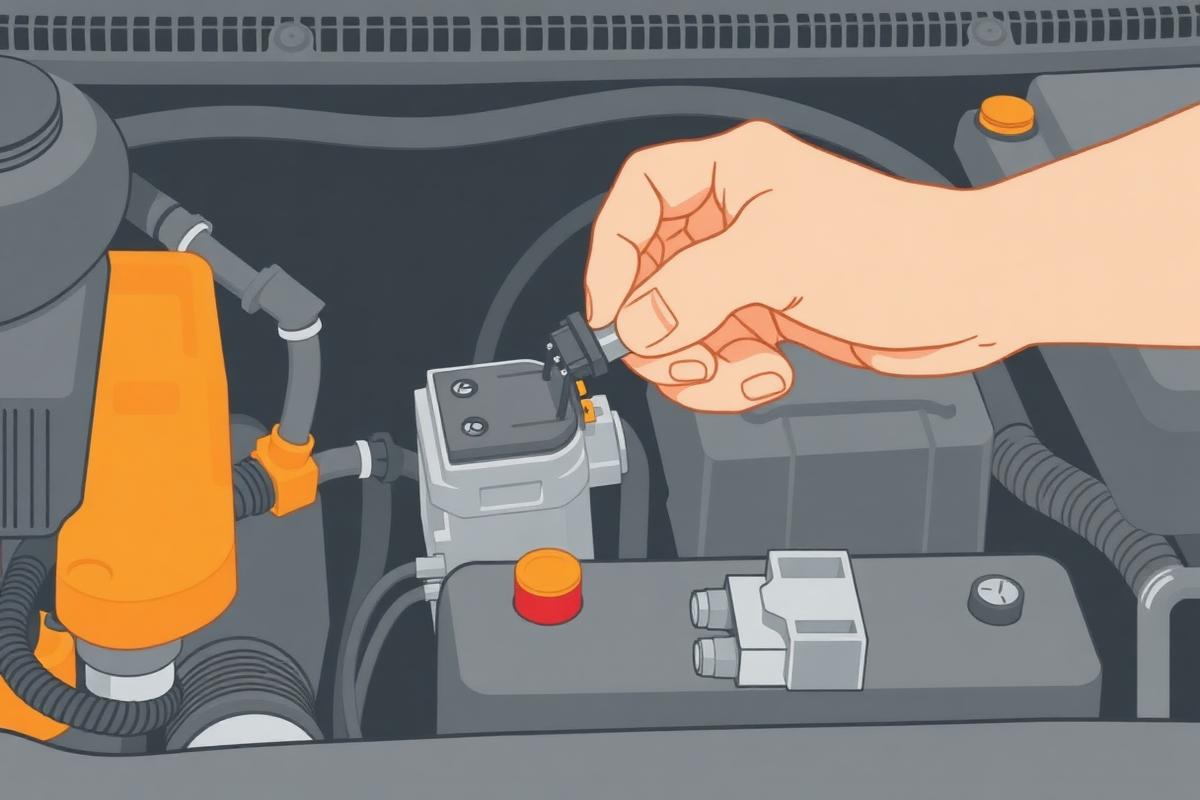
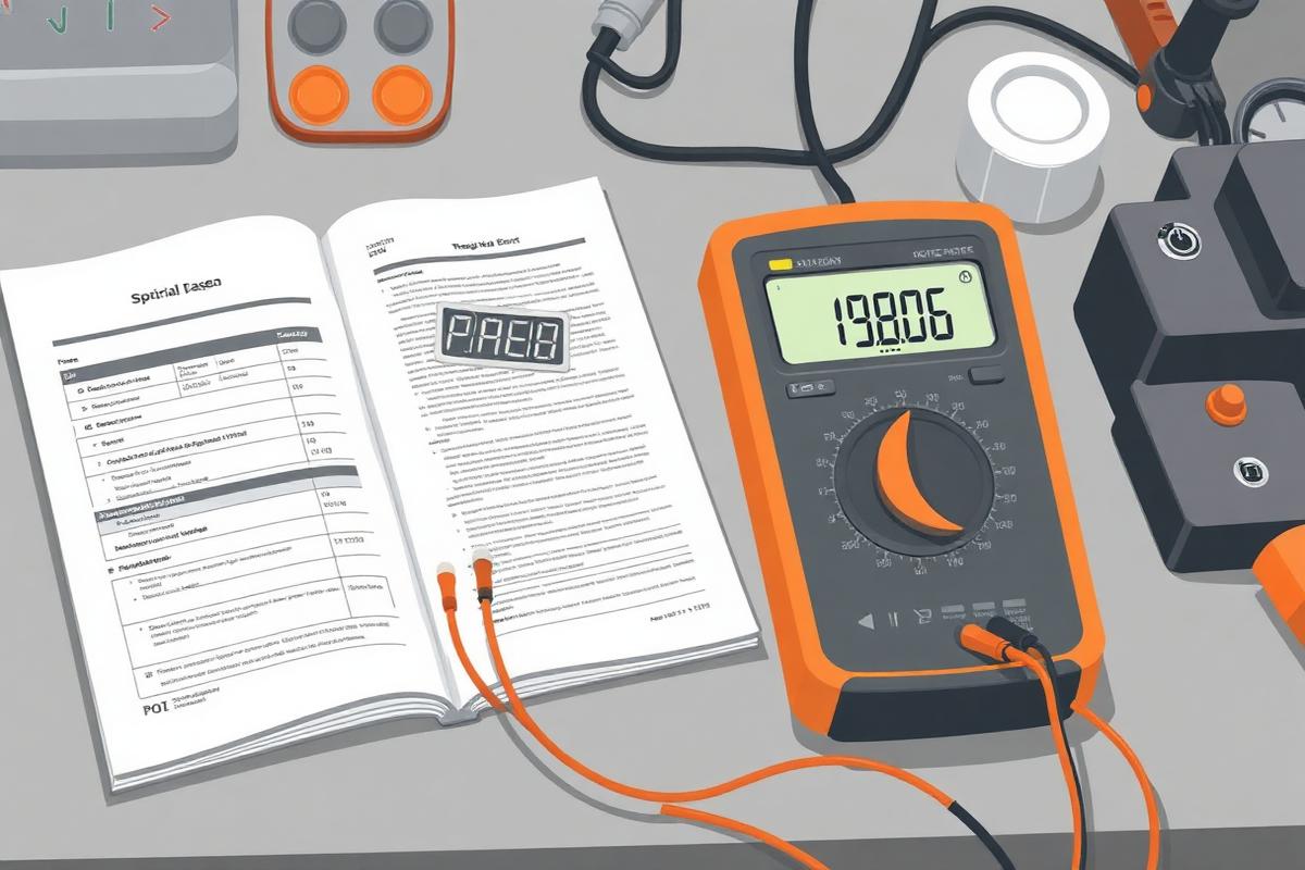
Step 1 · Isolate the component
Disconnect the battery or unplug the component. Any voltage present makes the reading meaningless and can damage the meter.
Never measure resistance on a live circuit.
Procedure
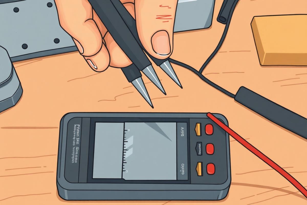
- Short the probes together and note the lead resistance, often 0.1 to 0.3 Ω
- Subtract that lead resistance from your measurements on low-value components
- Disconnect the component fully
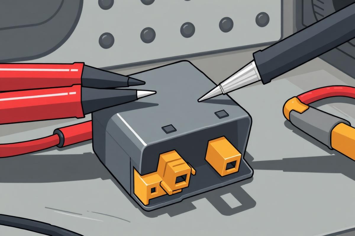
- Measure across the terminals and record the value
- Compare with the specification, and with an identical component on the vehicle where possible
- Check terminal to case for a short to the body
Normal result
Within the manufacturer's stated range at the stated temperature. Typical examples: a petrol injector around 12 to 16 Ω on a saturated driver, a relay coil around 60 to 120 Ω, and a coolant temperature sensor changing predictably with heat.
Fault result
Open circuit (OL) means the winding is broken. A value well below specification means shorted turns. Continuity to the case means a failed insulation.
Interpretation
IfReads OL or infinite
ThenThe winding or element is open
NextReplace the component
IfReads much lower than specification
ThenShorted turns — the component will draw excess current and may have damaged its driver
NextReplace, and check the controlling driver or circuit for damage
IfReads within specification but the component does not work
ThenThe component is electrically intact; the fault is in supply, ground, control, or mechanically inside it
NextMove to a power and ground check, then check the control signal
IfContinuity between terminal and case
ThenInsulation failure to the body
NextReplace the component
Common mistakes
- Measuring in circuit, so parallel paths pull the reading down
- Ignoring lead resistance on low-ohm components
- Ignoring temperature on sensors specified at a particular temperature
- Assuming a good resistance reading proves a good component — resistance says nothing about behaviour under load